Announcement

Collapse
No announcement yet.

Imp gauges again how they work and how to test them

Collapse
X
 
  • Filter
  • Time
  • Show
Clear All
new posts

  • Imp gauges again how they work and how to test them

    Well Imp gauges are not a mystery, nor are they truly electronic devices, quite the opposite they are primarily mechanical devices, no electrickery. Mechatronics is perhaps the term now days.

    If you want to delve into how stabilisers work and so on you can see more here, some of which is repeated in these videos

    MORE ON STABALISERS HERE

    Now.

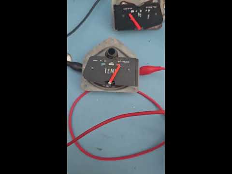
    These videos are in 2 parts, the first covers the stabilisers, gauges and how they work. Not complex and mostly done on my very messy work bench and although I have never had time to tidy it up it was fantastic to have the 1/2 hour or so enjoying the work.

    Part 1 - How things are wired and how they work.


    Thats the pseudo science covered

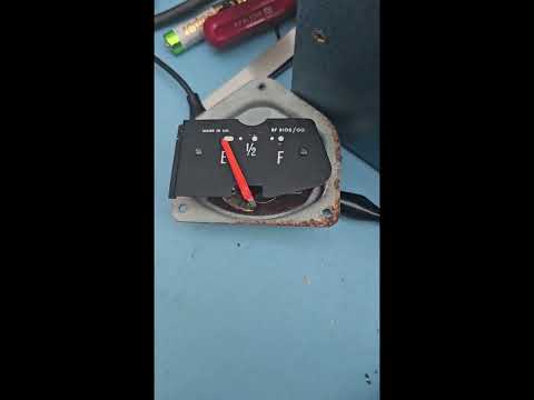
    How does this work in the car. Well you have 2 ends to test, you got to start somewhere

    Toward the end of the video we cover a specialised tool ( watch and see) that can be used to test the gauges in the car, remove wire from sender, connect to tester and then to chassis and off you go.

    Needs to be done with ignition ON and you need to pull the +VE on the coil or if you are unlucky and the points are closed you will bake your coil. You have been warned.

    Part 2 - demo and in car testing


    Enjoy


    Last edited by John A. Ross; 25 June 2024, 09:58 AM.
    / John

  • #2
    Hi John. Surely with all that kit you have you would be able to calibrate standard imp gauges for people I am thinking mainly of the temp gauge so that people know when the gauge is sat in mid position it reads for example 80 deg C. I am always worried that standard gauges are just really indicators rather than giving a temp, so if there was something wrong with the gauge or the stabiliser people could be driving round with the needle in the center of the gauge thinking all is good and they are 1 deg away from boiling over. You could offer an exchange service with a new sender and stabiliser tested on your bench. Supplied with some instructions on how to test the wire at the stabiliser end and the sender end to see if there is any resistance in the loom that could cause an inaccurate reading also. Would be piece of mind for people who do not want to install a known calibrated actual temp gauge that gave a reading in Deg C. I run a mechanical capillary tube gauge for temp and the fan is controlled by electrical means so I have defense in depth of a diversified system so if the electrical side has a damaged wire or a high resistance joint or sender issue and I notice the fans have not cut in a i can read the gauge and vice versa if the mechanical gauge starts reading low but the fans have cut in I know there is an issue with the gauge. Too many times you hear of people being happy that the gauge is at the 3/4 position so they are happy, what they do not know is has the gauge and stabiliser topped out and they are on the edge of boiling the engine. If you supplied a calibrated kit they would know center is for example 80 deg 3/4 is 90 deg and in the start of the red section is time to turn off an save engine.

    Comment


    • #3
      Mike

      Indeed, most gauges are not much more than indicators at there age as like the rest of us at 60, bending our backs back and forth every day takes its toll for that many years.

      But yes, it would be easy enough to calibrate them or at least get them a lot closer than they were.

      Using the same sender with the resistance map, would be easy enough to have 80 degrees dead centre.

      Actual temp wise the senders usually have a tolerance of +/- 2-5% and the mechanical gauges themselves 5-10%. They have 2 places to set the bend and getting it to track in a linear fashion takes a fair bit of fettling. It also assumes the tolerance of the stabiliser would be the same.

      If you want me to do any to try Mike just send me the sender you would use and a gauge and more than happy to do one.


      I always thought for an Imp best idea would be a hose mounted 200F/94C switch wired up to a buzzer


      A lot has been said about the imported cheap gauges available to buy from auction sites and these are electronic ones, I have found most of these I fitted were actually surprisingly good, same readings for 10-15V supply in although they needed a decent cable to the sender (2mm csa) to avoid the voltage drop on such a long length. The one I test fitted on my engine I also found was far better when I used a nylon reducer for the 1/8" sender, had to solder a second wire on for the body but without the block latent heat gave a far more accurate indication of fluid temp. Engine is out at moment and I plan to fit an inline fitting for the sender instead.

      Will see if i can pickup some temp gauges and maybe try a few on an exchange basis.

      The smiths stand alone gauges work the same way.

      John


      / John

      Comment

      Working...
      X